
TOFD is utilized for the rapid scanning of welds and the heat affected zones of in service components to detect their integrity. However, due to the software image utilized in TOFD, we normally recommend using Phased Array technology to image the defects once they have been detected using TOFD.
Time of Flight Diffraction (TOFD) is an advanced method of Ultrasonic inspection.
It is a very sensitive and accurate method for non-destructive testing of discontinuities in welded joints.
Time of Flight Diffraction (TOFD) ultrasonic test method can perform crack sizing very precisely and allow the owner to run the equipments or plants until the critical crack depth and length is not reached with a minimal risk of failure.
Conventional ultrasonic test method employs measuring of the amplitude of reflected signal which is relatively less reliable method of sizing defects because the amplitude strongly depends on the orientation of the crack.
Time of Flight Diffraction - TOFD ultrasonic test method uses the time of flight of an ultrasonic pulse to determine the position of a discontinuity of interest.
The Time of Flight Diffraction (TOFD) ultrasonic test system consists of a pair of probes placed on opposite sides of a weld.
One of the probes emits an ultrasonic pulse that is collected by the probe on the other side. In undamaged pipe, the signals picked up by the receiver probe are from two waves: one that travels along the surface and one that reflects off the far wall.
These ultrasonic waves are diffracted from the tip of the discontinuities, if present. The size of the discontinuity is calculated by measuring time of flight of the ultrasonic pulse.
Compared to conventional ultrasonic testing, Time of Flight Diffraction (TOFD) ultrasonic testing instruments and probes are complex and expensive and requires highly trained, skilled and experienced technicians.
WWOFI professionals are trained and experienced in Time of Flight Diffraction (TOFD) ultrasonic testing.

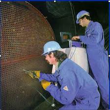 WWOFI Services provides a comprehensive inspection program consisting of multiple tube inspection techniques, to determine the integrity of heat exchanger tube bundles. Our extensive experience in heat exchanger inspection provides the assurance that components are properly evaluated to detect damage or defects thereby ensuring that tube bundles are safe to remain in operation. Failures can result in unplanned shutdowns, dangerous catastrophic failures or severe costly damage.
A variety of state of the art inspection methods such as: Eddy Current Testing (ET) of non-ferrous tubing and Remote Field Inspection (RFT) of ferrous tubing are supplied by WWOFI Services. A Remote Visual Inspection (RV) is typically employed for follow-up inspection of defective tubing to aid in root cause analysis.
EDDY CURRENT TESTING
WWOFI Services provides a comprehensive inspection program consisting of multiple tube inspection techniques, to determine the integrity of heat exchanger tube bundles. Our extensive experience in heat exchanger inspection provides the assurance that components are properly evaluated to detect damage or defects thereby ensuring that tube bundles are safe to remain in operation. Failures can result in unplanned shutdowns, dangerous catastrophic failures or severe costly damage.
A variety of state of the art inspection methods such as: Eddy Current Testing (ET) of non-ferrous tubing and Remote Field Inspection (RFT) of ferrous tubing are supplied by WWOFI Services. A Remote Visual Inspection (RV) is typically employed for follow-up inspection of defective tubing to aid in root cause analysis.
EDDY CURRENT TESTING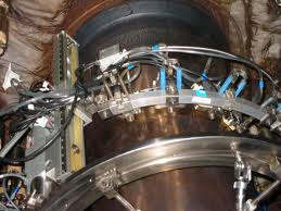 Automated Ultrasonic inspection offers many benefits to our client base and is utilized on capital projects, maintenance inspection, turnaround scheduling/planning and shutdown/turnaround/ outage situations. From high speed erosion/corrosion scanning systems using computer controlled ultrasonic scanners and software designed by our in house software engineers, highly sensitive P-Scan systems for accurate identification, location and sizing of defects in weld material and "on-line" inspection of various assets for prioritization in turnaround schedules, phased array ultrasonic inspection used for weld inspection in lieu of radiography and a variety of other applications, to high speed Time of flight Diffraction, WWOFI Services provides the appropriate ultrasonic inspection solution to your site. Some of the factors that we consider when recommending the appropriate ultrasonic technology are: the anticipated damage mechanism, operating condition of the asset, ability to access the area in question and the proximity of trade involvement to the inspection area.